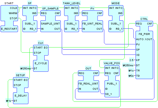
This system configuration implements the Model+View+Control
testing step for the process
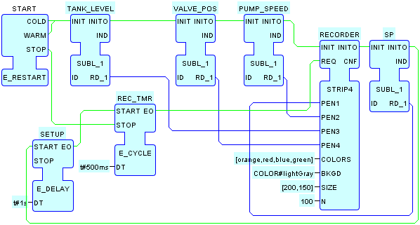
control example. It utilizes instances of the FACEPLATE, STRIP4, and FB_PIDR function block types to
simulate and display the Proportional/ Integral/ Derivative (PID)
control of liquid level in the process control
example.
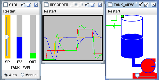
In Manual mode, adjusting the SP and PUMP sliders has the same effect on tank level as adjusting the VALVE and PUMP sliders, respectively, in the TANK_MVL configuration.
In Auto mode, the PID controller adjusts the Valve (OUT) position to hold the Tank level (PV) at the value specified by the SP slider, in the face of varying PUMP speeds.
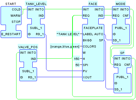
Set point (SP = PUMP_SPEED
), process variable (PV = TANK_LEVEL ),
controller output (OUT = VALVE_POS ), and
PUMP_SPEED
values are exchanged among resources using the local multicast pattern
and are plotted on the strip chart in colors of
orange
,
blue
,
green
and
red
, respectively.
The FBDK
uses the Tagged Data
design pattern to ensure consistency of the communicated events and
data, as shown in the table below. These are identical to the tags
used in the TANK_MVL
configuration, with the addition of the MODE and SP
tags.
| Name | Type | UDP Channel | Description |
|---|---|---|---|
MODE
|
BOOL
|
|
0=Manual, 1=Automatic
|
PUMP_POS
|
INT
|
|
{-359..+359} degrees
|
PUMP_SPEED
|
UINT
|
|
{0..100}% => {0..36} degrees per clock tick
|
SIM_CLK
|
|
|
Simulation Clock
|
SP
|
UINT
|
|
Set Point, {0..100}%
|
TANK_LEVEL
|
UINT
|
|
{0..100}%
|
VALVE_POS
|
UINT
|
|
{0..100}% => {closed..open}
|
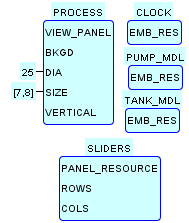
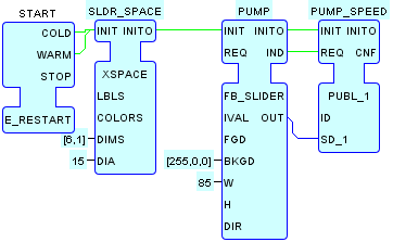
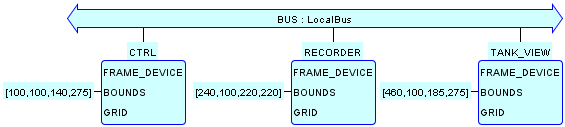
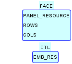
CTRL Device contains Resources for the PID
controller and its associated faceplate.
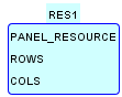
The only difference between the RECORDER device in this
configuration vs. the TANK_MVL
configuration is that the RECORDER.RES1 Resource
contains a four-channel stripchart recorder to accommodate the
additional SP variable to be plotted.
The only difference between the TANK_VIEW Device in
this configuration vs. the TANK_MVL
configuration is that the TANK_VIEW.SLIDERS Resource
does not contain a VALVE slider, since the valve position is
now determined by the controller output.