3. Animate operational sequences
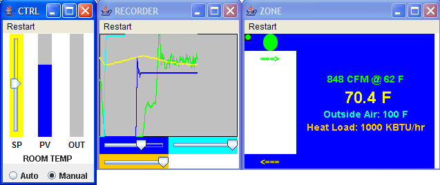
The graphic below shows the results of running the VAV_MVL system configuration with the
following sequence of events:
- The outside air is at 100F, and the heat load is at 100KBTU/hr, for
instance due to computer equipment in the room. The Variable Air Volume
(VAV) damper is closed, and the room temperature begins to rise.
- The VAV damper is opened to approximately 80% (note the simulated
sensor noise on the green trace). The room temperature begins to fall
toward the supply air temperature of 62F; it will not fall all the way
due to internal heat load in the room and heat transfer in through the
outside walls.
| Variable |
Channel |
Color |
| Room Temperature |
TEMP |
yellow |
| Flow Sensor |
DAMPER_SENSE |
green |
| Outside Air Temperature |
PARAMS.RD_1 |
cyan |
| Supply Air Temperature |
PARAMS.RD_2 |
blue |
 |
Last updated: 2006-04-25.
©2006 Holobloc
Inc
Licensed under the Academic Free
License version 3.0.