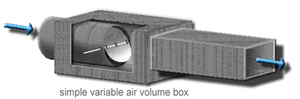
The Variable Air Volume (VAV) unit shown below is to be used for heating and/or cooling of a HVAC zone. The VAV unit control utilizes:
The velocity sensor, damper and actuator and controller are typically installed in the ceiling and receive conditioned air (supply air) from above ceiling duct work. The controlled air is directed to the zone that is being controlled through diffusers that are connected to the output side of the VAV unit. The zone temperature sensor and set point are usually mounted on a wall in the space being controlled. Generally this is called a "thermostat"; however, this is not to be confused with a true thermostat which also contains a temperature control function.
If an optional sensor is provided to measure the supply air temperature Ts, this can be used to determine the control regime as follows:
HEATING = (SP > T) AND (Ts > T)
COOLING = (SP < T) AND (Ts < T)
VENTILATION = NOT HEATING AND NOT COOLING